CA3080 vs LM13700: Exploring the Differences and How to Choose
 Published: Nov 29, 2023
Contents
Introduction
In this article, our team Avaq offers a comparative analysis between the CA3080 and LM13700 integrated circuits, essential components in electronic engineering. It outlines the distinct features and applications of each, emphasizing the critical need to discern their differences. By delving into their functionalities, applications, and performance variations, this piece aims to assist electronic enthusiasts and engineers in making informed choices for their circuit designs based on the unique attributes of these ICs.
Here's the video about 3080 vs 13700 explained,
Understanding the CA3080
1. Introduction to the CA3080 IC
The CA3080 and CA3080A ICs mark a significant advancement in Gatable-Gain Blocks, leveraging the distinctive operational-transconductance-amplifier (OTA) concept elucidated in Application Note ICAN-6668, "Applications of the CA3080 and CA3080A High-Performance Operational Transconductance Amplifiers." These components are characterized by a differential input and a single-ended, push-pull, class A output configuration. Additionally, they incorporate an amplifier bias input that offers adaptability for both gating and linear gain control functionalities.
Notably, they exhibit a high output impedance, and their transconductance (gM) directly corresponds to the amplifier bias current (IABC), ensuring precision in their functionality. Highlighting an exceptional slew rate of 50V/µs, these components excel in multiplexer applications and swift unity-gain voltage followers, operating with power consumption only in the "ON" channel state.
Moreover, the CA3080A variant is rated for full military-temperature range operation (-55oC to +125oC) and is finely tuned for sample-hold, gain-control, and multiplexing applications. Expanding their utility, operational transconductance amplifiers, as described in Application Note AN6048, "Some Applications of a Programmable Power Switch/Amplifier" (CA3094, CA3094A, CA3094B), also prove beneficial in programmable power-switch scenarios, showcasing their versatility across various electronic applications.
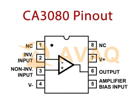
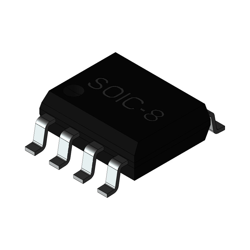
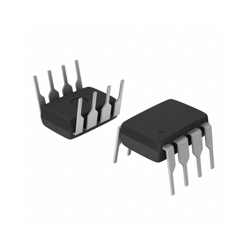
2. CA3080 Pinout
Pinout Details
|
Pin No. |
Description |
Pin Name |
|
1, 8 |
Not connected |
NC |
|
2 |
Inverting Input |
IN - |
|
3 |
Non-inverting Input |
IN + |
|
4 |
Ground |
GND |
|
5 |
Amplifier bias input |
Ibias |
|
6 |
Output |
Output |
|
7 |
Voltage supply |
Vcc |
3. Specifications and Features
- Achieving a Slew Rate of 50V/µs (Unity Gain, Compensated)
- Adjustable Power Consumption Ranging from 10µW to 30µW
- Versatile Supply Voltage Range: ±2V to ±15V
- Complete Adjustability of Gain: From 0 to gMRL Limit
- Precise gM Spread: CA3080: Maintaining a Tight Ratio of 2:1
- Extending gM Linearity Across 3 Decades
4. Applications in different electronic circuits or systems
Applications
- Sample and Hold Circuits: Utilized for maintaining and storing an analog signal at a specific point in time, crucial in analog-to-digital conversion processes, waveform capturing, and signal processing applications.
- Multiplier Configurations: Employed in analog multiplier circuits, facilitating the multiplication of two input signals, prevalent in modulation, frequency mixing, and various signal processing tasks.
- Multiplexer Operations: Integral component in multiplexers, enabling the selection and routing of multiple analog signals through a single channel or line, common in data acquisition systems and telecommunications.
- Comparator Functions: Engaged in comparison tasks, where it evaluates two voltage signals and determines their relationship, pivotal in instrumentation, threshold detection, and feedback control systems.
- Voltage Follower Applications: Deployed as unity-gain buffers, maintaining the same voltage as the input signal, minimizing load effects, and widely utilized in impedance matching, signal buffering, and isolation circuits.
Applications in Different electronic circuits
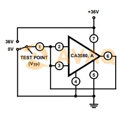
LEAKAGE CURRENT TEST CIRCUIT
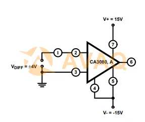
DIFFERENTIAL INPUT CURRENT TEST CIRCUIT
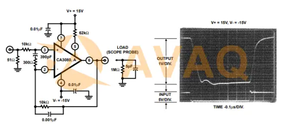
THE CA3080 AND CA3080A IN A UNITY-GAIN
VOLTAGE FOLLOWER CONFIGURATION AND ASSOCIATED WAVEFORM
Understanding the LM13700
1. Introduction to the LM13700 IC
The LM13700 stands as an integrated circuit comprising two current-controlled operational transconductance amplifiers (OTAs), each featuring differential inputs and a push-pull output. Differing from a standard op-amp, an OTA operates with voltage in and current out, and its behavior can be programmed via the IABC pin. Linearizing diodes at the input serve to minimize distortion and enable higher input levels. Specifically engineered darlington output buffers complement the OTA's wide dynamic range.
This chip finds extensive utility in audio electronics, notably in analog synthesizer circuits such as voltage-controlled oscillators, voltage-controlled filters, and voltage-controlled amplifiers. The darlington output buffers on the LM13700 differ from those on the LM13600 as their bias currents, and hence their output DC levels, operate independently of the IABC pin. This characteristic can result in superior performance compared to the LM13600, particularly in audio applications.
2. LM13700 IC Pinout
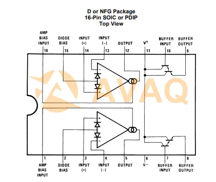
Pin Functions
|
Pin No. |
I/O Description |
Name |
|
1, 16 |
A Current bias input |
Amp bias input |
|
7, 10 |
A Buffer amplifier input |
Buffer input |
|
8, 9 |
A Buffer amplifier output |
Buffer output |
|
2, 15 |
A Linearizing diode bias input |
Diode bias |
|
3, 14 |
A Positive input |
Input+ |
|
4, 13 |
A Negative input |
Input– |
|
5, 12 |
A Unbuffered output |
Output |
|
11 |
P Positive power supply |
V+ |
|
6 |
P Negative power supply |
V- |
3. Technical specifications and features
Specifications
- Number of channels: 2
- Total supply voltage (max): 36V
- Total supply voltage (min): 10V
- Rail-to-rail: No
- Gain-Bandwidth Product (GBW): 2 MHz
- Slew rate: 50 V/µs
- Offset voltage (max) at 25°C: 4 mV
- Quiescent current per channel (typ): 1.3 mA
- Rating: Catalog
- Operating temperature range: 0 to 70°C
- Offset drift (typ): 0 µV/°C
- Maximum input bias current: 5,000,000 pA
- Common-Mode Rejection Ratio (CMRR) (typ): 110 dB
- Output current (typ): 0.02 A
- Architecture: Bipolar
- Input common mode headroom (to negative supply): 0V
- Input common mode headroom (to positive supply): 0V
- Output swing headroom (to negative supply): 0V
- Output swing headroom (to positive supply): 0V
Features
- Adjustable gM Across 6 Decades
- Outstanding gM Linearity
- Precise Matching Between Amplifiers
- Linearizing Diodes for Minimized Output Distortion
- High-Impedance Buffers
- Elevated Output Signal-to-Noise Ratio
4. Applications
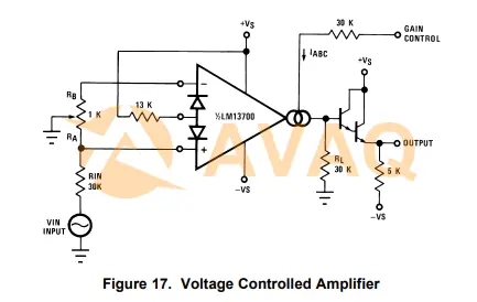
- Current-Controlled Amplifiers
- Stereo Audio Amplifiers
- Current-Controlled lmpedances
- Current-Controlled Filters
- Current-Controlled Oscillators
- Multiplexers
- Timers
- Sample-and-Hold Circuits
Differences between CA3080 and LM13700
Specifications
|
Specification |
CA3080 |
LM13700 |
|
Functionality |
Gatable-Gain Block |
Dual Operational Transconductance Amplifiers (OTAs) |
|
Configuration |
Single operational transconductance amplifier |
Dual OTAs within a single chip |
|
Outputs |
Push-pull, class A output |
Push-pull output for each OTA |
|
Input/Output Channels |
Single-channel |
Dual-channel (two integrated OTAs) |
|
Supply Voltage Range |
±2V to ±15V |
±5V to ±18V |
|
Slew Rate |
50V/µs |
50V/µs |
|
Offset Voltage (max) |
4 mV |
- |
|
Gain-Bandwidth Product (GBW) |
2 MHz |
- |
|
Input Bias Current (max) |
- |
5,000,000 pA (per channel) |
|
Common-Mode Rejection Ratio (CMRR) |
- |
110 dB (typical) |
|
Operating Temperature Range |
0 to 70°C |
0 to 70°C |
Main Difference between CA3080 and LM13700
Functionality:
- CA3080: Designed as a Gatable-Gain Block primarily used in voltage-controlled amplifiers, filters, and oscillators.
- LM13700: Consists of dual Operational Transconductance Amplifiers (OTAs), commonly applied in audio circuits like synthesizers for filters, oscillators, and amplifiers.
Configuration:
- CA3080: Features a single operational transconductance amplifier.
- LM13700: Integrates two OTAs within a single chip, providing dual-channel capabilities.
Outputs:
- CA3080: Offers a push-pull, class A output.
- LM13700: Presents push-pull outputs for each OTA, allowing independent control.
Components Usage:
- CA3080: Leverages the operational transconductance amplifier concept for specific applications like gating or linear gain control.
- LM13700: Utilizes OTAs with voltage in and current out behavior, programmable through the IABC pin.
Applications:
- CA3080: Suited for systems requiring gatable gain blocks, multiplexers, and voltage followers.
- LM13700: Widely used in audio electronics, particularly in synthesizer circuits for its OTA-based functionalities in filters, oscillators, and amplifiers.
Number of Channels:
- CA3080: Typically a single-channel device.
- LM13700: Houses two OTAs, providing dual-channel capabilities.
Advantages and disadvantages of each IC CA3080 and LM13700
CA3080
Advantages:
- Gatable-Gain Block: Specifically designed for gatable gain applications, useful in voltage-controlled amplifiers and filters.
- Low Power Consumption: Efficient power usage when compared to some alternatives.
- High Slew Rate: 50V/µs slew rate makes it suitable for multiplexers and fast voltage followers.
- Excellent for Audio: Well-suited for audio applications and voltage-controlled systems.
Disadvantages:
- Limited Functionality: Specialized for gatable gain applications, limiting versatility in broader circuits.
- Single Channel: Typically operates as a single-channel device, constraining applications requiring multiple channels.
LM13700
Advantages:
- Dual OTAs: Contains two OTAs within a single chip, providing dual-channel capabilities.
- Audio Circuit Applications: Widely used in audio systems for filters, oscillators, and amplifiers.
- Versatile Programming: Programmable OTAs via the IABC pin, allowing flexibility in design.
- High Input Impedance: Suitable for various input signal configurations.
Disadvantages:
- Higher Power Consumption: Compared to some alternatives, it may consume relatively more power.
- Complexity: Dual-channel design might increase circuit complexity in some applications.
Key Factors Influencing the Choice between CA3080 and LM13700
When choosing between the CA3080 and LM13700 integrated circuits, several key factors come into play:
CA3080:
- Gatable Gain Applications: Ideal for circuits requiring gatable gain blocks, voltage-controlled amplifiers, and filters.
- Single-Channel Requirement: Suitable when a single-channel operational transconductance amplifier suffices for the application.
- Low Power Consumption: If power efficiency is a priority compared to other alternatives.
- Specific Audio Applications: Suited for audio-related circuits like voltage-controlled systems.
LM13700:
- Dual OTA Requirement: Need for dual-channel operational transconductance amplifiers within a single chip.
- Audio Circuit Design: Specifically useful in audio systems for filters, oscillators, and amplifiers.
- Versatile Programming: When the flexibility of programmable OTAs via the IABC pin is desired.
- Higher Input Impedance: Applications that benefit from higher input impedance configurations.
Datasheet PDF
Conclusion
In exploring the differences between the CA3080 and LM13700 integrated circuits, it becomes evident that each possesses unique characteristics tailored for distinct applications. The CA3080, designed as a specialized gatable gain block, excels in single-channel configurations, making it particularly suitable for voltage-controlled amplifiers and filters. Its emphasis on power efficiency and suitability for audio systems highlights its niche in specific electronic designs.
Conversely, the LM13700, housing dual Operational Transconductance Amplifiers (OTAs) within a single chip, stands out for its versatility in dual-channel applications, especially in audio circuitry for filters, oscillators, and amplifiers. Its programmability via the IABC pin and higher input impedance expand its usability in various circuit configurations.
Selecting between these ICs necessitates a deep understanding of the circuit requirements. The CA3080's strengths lie in its focused gatable gain functionality and efficiency, while the LM13700's advantage lies in its dual-channel versatility and adaptability in audio circuits.
Ultimately, the best-suited IC depends on the specific demands of the electronic system. Careful consideration of factors like channel requirements, power efficiency, and intended applications ensures the optimal choice, enabling seamless integration and superior performance within the targeted circuit design.
Next Industry Focus
IC 7815 Voltage Regulator: Pinout, Datasheet and How to Use
 Update Time: Dec 01, 2023 Consumer Electronics
 FAQ
FAQ
- Are there any design considerations when choosing between the CA3080 and LM13700?
- Depending on the specific circuit requirements, performance expectations, and available space, choosing between the two should be based on their individual specifications and how they fit within the intended application.
- Which one is better for audio applications?
- The LM13700 is generally favored for audio applications due to its dual OTA configuration, higher transconductance, and better linearity compared to the CA3080.
- Can use the CA3080 and LM13700 interchangeably?
- In some circuits, they can be used interchangeably, but there might be differences in performance and specifications. The LM13700 generally offers better performance and additional features compared to the CA3080.
Related Industry Focus
-

PT2399 IC Delay Echo Audio Processor: Datasheet, Pinout and Application
The PT2399 is a versatile CMOS single-chip echo processor integrated circuit, renowned for its functionality in creating delay effects. This digital chip incorporates an ADC (Analog-to-Digital Converter) that seamlessly converts incoming analog audio signals into a bina...
Published: 2023-11-27 17:31:41 -
JRC4558 vs TL072: What are Differences and How to Choose
In this article, we will compare and contrast the JRC4558 and TL072 op-amps, exploring their features, specifications, and applications to guide your selection process for various audio-related projects.
Published: 2023-11-24 18:12:00 -
VIPER12A IC Pinout, Circuit, Datasheet and Equivalent (Pin Video Attached)
The VIPER12A stands as a comprehensive SMPS controller IC featuring an integrated PWM controller paired with a potent power MOSFET on a single silicon chip. This integration enables efficient conversion of a wide AC input voltage range spanning from 85V to 265V into low...
Published: 2023-11-22 16:29:02 -
![KSC1845 Transistor: Equivalent, Datasheet and Pinout [FAQs]](/files/uploads/technology/b/20231120174333ksc1845 transistor-pinout.webp)
KSC1845 Transistor: Equivalent, Datasheet and Pinout [FAQs]
The KSC1845 belongs to the NPN transistor family, a type of bipolar junction transistor commonly packaged in TO-92 format and crafted from silicon semiconductor material.
Published: 2023-11-20 17:45:55
LM13700MX/NOPB In Stock: 5333
 Popular Industry Focus
Hot Products
-
CC3220SF12ARGKR
Texas Instruments, Inc
SimpleLink™ 32-bit Arm Cortex-M4 Wi-Fi® wireless MCU with 1MB Flash and 256kB RAM
-
DS90LV011AQMF/NOPB
Texas Instruments, Inc
Automotive LVDS differential driver
-
LMH6722MAX/NOPB
Texas Instruments, Inc
Quad Channel, Wideband Video Amplifier
-
TLV320AIC12KIDBTR
Texas Instruments, Inc
Low-Power Mono Voice Band CODEC with 8-ohm Speaker Amplifier
-
DS92LX2121SQE/NOPB
Texas Instruments, Inc
10-MHz to 50-MHz DC-balanced Channel Link III Bi-Directional control serializer
-
DAC0808LCN/NOPB
Texas Instruments, Inc
8-Bit D/A Converter
Related Parts
-
LMH6722MAX/NOPB
Texas Instruments, Inc
Quad Channel, Wideband Video Amplifier
-
HMC387MS8TR
Analog Devices, Inc
Up/Down Conv Mixer 500MHz 8-Pin MSOP
-
AD8330ARQZ-R7
Analog Devices, Inc
Low Cost, DC to 150 MHz, Variable Gain Amplifier
-
LT1739CFE#PBF
Analog Devices, Inc
Dual 500mA, 200MHz xDSL Line Driver Amplifier
-
INA190A4IRSWT
Texas Instruments, Inc
40-V, bidirectional, ultraprecise current sense amplifier with picoamp IB & ENABLE
-
LMH6722MTX/NOPB
Texas Instruments, Inc
Quad Channel, Wideband Video Amplifier
-
SN10501DR
Texas Instruments, Inc
High Speed Operational Amplifiers Lo-Distortion Hi-Spd R-to-R Otpt Oper Amp
-
HA3-2841-5
Renesas Technology Corp
Operational Amplifiers - Op Amps
-

LMV321WG-7
DIODES
General Purpose Amplifier 1 Circuit Rail-to-Rail SOT-25
-
OPA656U
Texas Instruments, Inc
Voltage Feedback Amplifier 1 Circuit 8-SOIC
-
MCP6549-I/SL
Microchip Technology, Inc
Open-Drain Output Sub-Microamp Comparators.
-
TLV2362IDR
Texas Instruments, Inc
Dual, 5-V, 7-MHz, low noise (8-nV/√Hz) operational amplifier
-
LM2903FVM-TR
ROHM Semiconductor
Comparator Dual ±16V/32V 8-Pin MSOP T/R
-
OPA615IDGST
Texas Instruments, Inc
Wide Bandwidth, DC Restoration Circuit
-
AD621AN
Analog Devices, Inc
Instrumentation Amplifier, 1 Func, 185uV Offset-Max, 0.2MHz Band Width, BIPolar, PDIP8
Featured Manufacturers