Microchip PIC18F25K80 based OBDII Solution
 Published: Apr 27, 2023
Automotive Electronics
Share:
Published: Apr 27, 2023
Automotive Electronics
Share:
Since the 1980s, major automobile manufacturers in the U.S., Japan and Europe began to equip OBD on their EFI vehicles, and the initial OBD did not have a self-test function. OBD-II, which is more advanced than OBD, was produced in the mid-1990s.
The Society of Automotive Engineers (SAE) developed a set of standard specifications, requiring each automobile manufacturer to provide a unified diagnostic mode according to the OBD-II standard, and in the late 1990s, all cars entering the North American market were set up with OBD according to the new standard.
OBD-II differs from all previous on-board diagnostic systems in that it is strictly emission-specific, and its substantive function is to monitor the vehicle's emissions by monitoring the vehicle's power and emission control systems.
When a vehicle's power or emission control system fails, potentially causing carbon monoxide (CO), hydrocarbons (HC), nitrogen oxides (NOx) or fuel evaporation pollution to exceed set standards, a fault light will illuminate to alert.
Features of OBDII:
- 1. Uniform vehicle type diagnostic seat shape of 16PIN.
- 2. With numerical analysis data transmission function (DATA LINK CONNECTOR, DLC for short).
- 3. Unify the same fault code and meaning for each vehicle type.
- 4. With the function of driving recorder.
- 5. With the function of re-displaying the memory fault code.
- 6. With the function of clearing the fault code directly by the instrument.
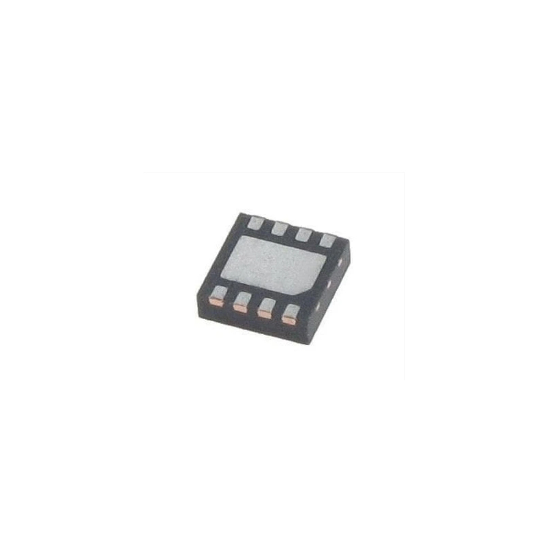
U.S. Microchip pic18F25K80 has low power consumption, small size, rich peripheral characteristics.
1 pic18F25K80 power consumption during sleep is nA level.
Low-power applications are a key consideration in OBDII solutions because the automotive OBD interface is permanently powered
It will be powered even after the engine is turned off. Therefore, if the OBDII solution is designed without considering the power consumption, the car owner will lose power once the car is not used for a long time. If you don't use the car for a long time, it will cause the car level to lose power and can't start.
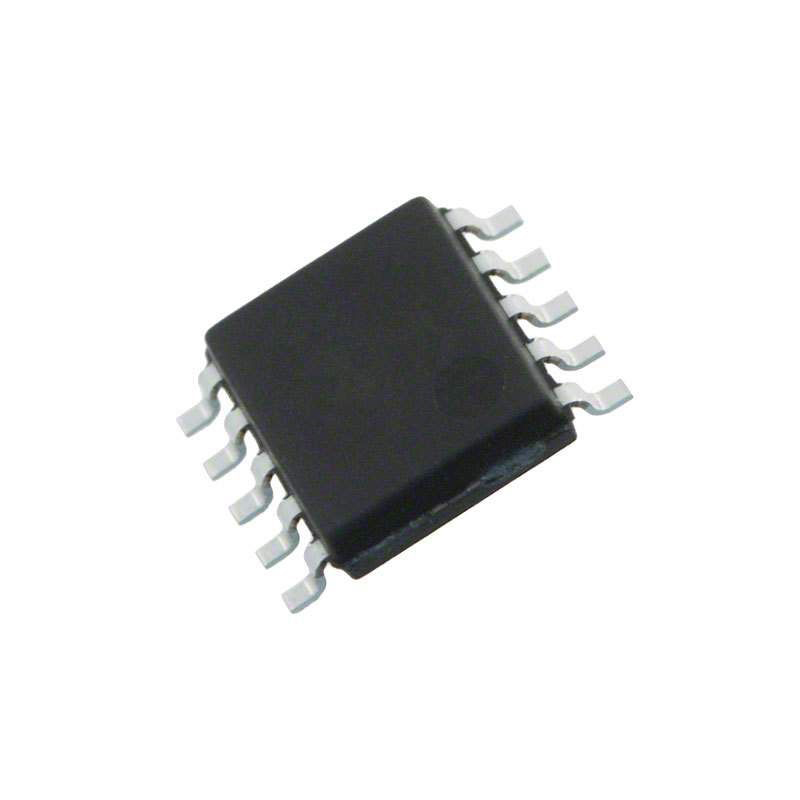
2 pic18F25K80 has Can bus interface only need to cooperate with a canbus driver (MCP2561) to complete the minimum of the hardware link layer of Canbus interface
3 pic18F25K80 has dual serial ports and 32K flash, 3.6K RAM to facilitate the expansion of OBDII module, which can be connected to BT, WIFI, etc. via serial port. The 32K flash also allows engineers to use it more easily.
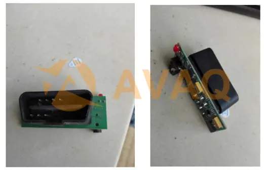
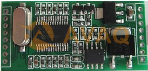
►Product physical picture
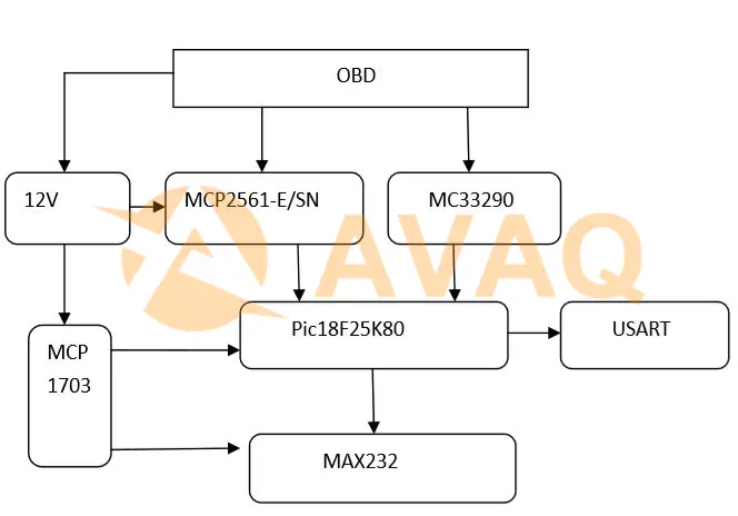
►Program square diagram
►Core technical advantages
- Operating voltage: DC 9-12V
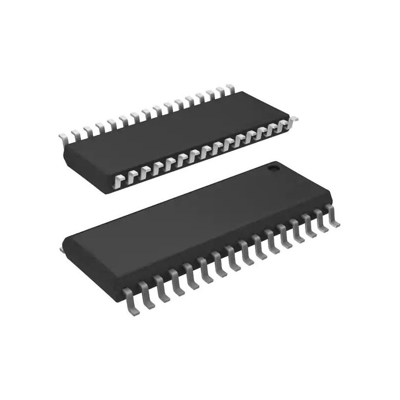
- Use pic18F25K80-I/SS
- Support two Canbus
- Support serial port
- Support OBDII bus protocol
►Solution specification
Using PIC18F25K80 to read parameters through Canbus K-line Canbus train receiver
using MCHP MCP2561 MCU power supply part using MCP1703
Next Solutions
Smart Car Tracker Solution based on ST STM32F101RCT6 and LIS3DHTR
 Update Time: Apr 27, 2023 Consumer Electronics
Recommend Products

Related Solutions
-
NXP Introduces High-Power Wireless Charg...
NXP Semiconductors announced the first high-power wireless charging solution for notebooks and 2-in-...
Apr 28, 2023 Consumer Electronics -

Multifunctional Street Light Automatic C...
The street light automatic controller is suitable for the automatic control of street lights in resi...
Apr 26, 2023 Consumer Electronics -

How Can IoT Solution Providers Build a S...
The Internet of Things (IoT) has been attracting a lot of attention in the industry for its security...
Apr 25, 2023 Consumer Electronics -
ADI Proposes a Solution for Servo Motor ...
For motor control solutions, ADI offers a comprehensive portfolio of products, including analog-to-d...
Apr 25, 2023 Consumer Electronics -
IoT Transforms and Adds Value to Consume...
The Internet of Things (IoT) is taking consumer electronics to another level and could lead to the n...
Apr 26, 2023 Consumer Electronics -
Texas Instruments Programmable Logic and...
Programmable logic controllers (PLCs) and programmable automation controllers (PACs) process and con...
Apr 26, 2023 Consumer Electronics