Multifunctional Street Light Automatic Control Circuit Solution
 Published: Apr 26, 2023
Automation & Control
Share:
Published: Apr 26, 2023
Automation & Control
Share:
The street light automatic controller is suitable for the automatic control of street lights in residential living quarters, schools, hotels and other places, solving the long light in public places and achieving the purpose of energy saving.
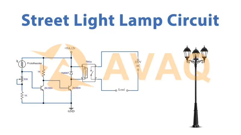
Control Principle
1. All-night light control
Turn off the light part: all-night light is the day off and night on the general-purpose automatic control. In the transition from night to day, the sky is gradually brightened by darkness, the internal resistance of the photo resistor RG2 decreases, the potential of the positive input of IC2A drops, and when it is lower than the potential of the negative input, the voltage comparator composed of IC2A and IC2B outputs a low potential, and the triode V3 turns on and off from the original.
Power supply through W4, R12 to C8 charging. The delay begins, the delay time adjustable W4, about 2 to 5 minutes or so. At this time, the positive input potential of IC6 rises, to be higher than the negative input potential when IC6 output high potential, transistor V2 conduction, relay J3 suction, J3-1 cut off the power supply of relay J1 so that J1 release, J1-1 disconnect, turn off the street light. As the change of natural light from night to day is very slow, it will go through an unstable process, which will cause the street light to close, the delay is to avoid the slow change from dark to light and cause the critical state instability, to turn off the light quickly and thoroughly.
Turn on the light part: when the transition from day to night, the light gradually darkened.
RG2 internal resistance increases, IC2A output high potential due to rising potential of the positive input, IC2B output high potential, triode V3 from the original cut-off into conduction, C8 by R12 and V3 discharge, IC6 positive input potential quickly drop, so that IC6 output low level, triode V2 cut-off, relay J3 release, J3-1 on the SCR VR forward voltage. As the light continues to darken photoresistor RG1 resistance increases, C3 charging, IC2C positive input potential slowly rise, when the positive input potential is higher than the negative input potential, IC2C output high level, IC2D output high level, R5, C4 differential circuit output positive pulse will be triggered on the SCR, relay J1 suction, contact J1-1 on, the street light on.
2. Midnight lights and morning and evening lights control
The so-called "midnight light" is to turn off all or part of the street lights at midnight when there are few pedestrians. IC5 and R8, W2, W3, C7 form the clock oscillation, IC5 is a high-precision controller that can generate precise timing pulses, and its output pulse is determined by R8, W2, W3, C7. IC4C, R7, G6 form the power-on rezero circuit, so that the divider IC3 is all-zero output state. IC4B is a blocking circuit that prohibits clock pulses from being sent to IC3's ⑩ pin (CL terminal) after the timing ends. IC5 starts when J3-1 is turned on, and the oscillation period is adjusted from W2 to 1.75 seconds. When 8192 pulses are counted, 4 hours of timing is completed, and if the oscillation period is 2.63 seconds, 6 hours of timing is completed.
IC3 to IC5 oscillation pulse counting, in the count to 8192 pulses IC3 ③ pin (Q14) output high level control of the two branches, one way to make the transistor V1 conduction, relay J2 suction, J2-1 disconnect, close part of the street lights or all street lights. At the same time, the other way through the gate IC4B closed IC4A prohibited to continue counting. This is the "midnight light". 4 hours timer for summer, 6 hours timer for winter, K2 is the winter and summer changeover switch.
If you disconnect K1 will cancel the blockade, turned into a cycle of delay circuit, appropriate adjustment of the delay, so that the lights are turned off at midnight, darkness before dawn and then turn on the lights, which is the "morning and evening lights". This "morning and evening light" solves the problem of lighting in the dark stage before dawn. It is convenient for people who get up early. After dawn, the lights are automatically turned off again.
The Selection of Components
IC1; choose three-terminal voltage regulator 7812, IC2: choose four voltage comparator LM339, IC3: choose fourteen binary counter CD4020, IC4: choose four two input and non-gate CD4011, IC5: choose NE555 time base circuit, IC6: choose LM311 voltage comparator. w1 ~ w5 choose wire-wound potentiometer. rg1, rg2 choose Q14 CdS Photoresistor. Relay J1, J2 choose high-power JQX-15F, contact: AC22V/30A. J3 choose a miniature relay with normally closed contact. The electrolytic capacitors are ordinary electrolytic capacitors except for C3 and C8, which are bile electrolytic capacitors. The resistors are 1/4W, and the diode is 1N4001.
Debugging
The first step: in setting the environment to turn off the lights, first adjust W5 so that IC2A, IC2B voltage comparator output low potential, and then adjust W4 so that the delay is about 5 minutes J3 release off the street lights. The second step: to two photoresistors to cover the light (simulated night) in J3 release, in the case of not connected to C3, adjust Wl so that IC2D output high, J1 suction, turn on the street lamp. Step 3: Turn on K2 in J3 release state, adjust W2 delay for about 4 hours, turn on K2 and adjust W3 delay for about 6 hours. Repeat the debugging to reach the best state.
Next Solutions
Basic Introduction of IoT (Internet of Things)
 Update Time: Apr 26, 2023 Consumer Electronics
Recommend Products
Related Solutions
-
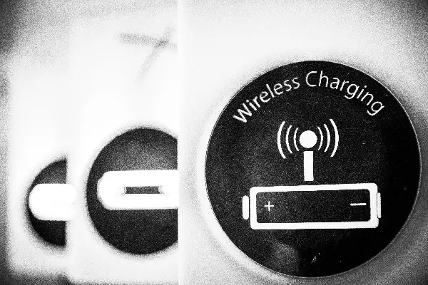
NXP Introduces High-Power Wireless Charg...
NXP Semiconductors announced the first high-power wireless charging solution for notebooks and 2-in-...
Apr 28, 2023 Consumer Electronics -

Multifunctional Street Light Automatic C...
The street light automatic controller is suitable for the automatic control of street lights in resi...
Apr 26, 2023 Consumer Electronics -

How Can IoT Solution Providers Build a S...
The Internet of Things (IoT) has been attracting a lot of attention in the industry for its security...
Apr 25, 2023 Consumer Electronics -
ADI Proposes a Solution for Servo Motor ...
For motor control solutions, ADI offers a comprehensive portfolio of products, including analog-to-d...
Apr 25, 2023 Consumer Electronics -

IoT Transforms and Adds Value to Consume...
The Internet of Things (IoT) is taking consumer electronics to another level and could lead to the n...
Apr 26, 2023 Consumer Electronics -

Texas Instruments Programmable Logic and...
Programmable logic controllers (PLCs) and programmable automation controllers (PACs) process and con...
Apr 26, 2023 Consumer Electronics