Introduction to Darlington Transistors -- TIP122 Example
 Published: Jun 30, 2023
Contents
Darlington transistors are a type of bipolar junction transistor (BJT) configuration that offers high gain and current amplification. The Darlington transistor pair, consisting of two bipolar transistors connected in a specific way, provides improved performance characteristics compared to a single BJT. One popular example of a Darlington transistor is the TIP122, which offers high current capability and is commonly used in various applications, including motor control, solenoid driving, and power switching.
In this article, we will introduce the concept of Darlington transistors and explore the TIP122 as an example, highlighting its features, advantages, and applications. Whether you are an electronics enthusiast, a hobbyist, or a professional engineer, understanding the fundamentals of Darlington transistors and the capabilities of the TIP122 will empower you to incorporate them effectively into your circuit designs and achieve superior performance.
Darlington Transistor Working Principle
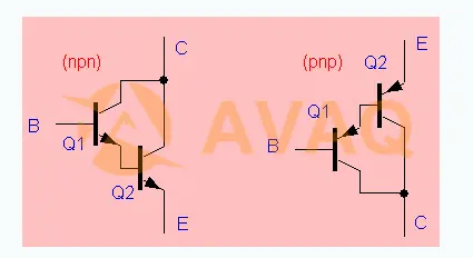
Darlington transistor, which is a high gain bipolar power transistor, is in essence a Darlington or super a pair (darlington pair or Pmultip丨er) composed of two or more transistors, the emitter of one transistor in the composite pair is connected to the base of the next transistor, and the collectors of each transistor are connected together, showing that this combination can be regarded as an Equivalent transistor, the gain is equal to the product of the gain of each transistor.
The Darlington transistor contains two BJTs that are connected to provide high current gain from a low base current. In this transistor, the emitter i/p of the transistor is connected to the base o/p of the transistor and the collectors of the transistors are connected together. Thus, transistor i/p amplifies the current and even further amplifies the current through transistor o/p.
Darlington transistors are classified into different types according to power consumption, maximum CE voltage, polarity, minimum DC current gain and package type. Common values of maximum CE voltage are 30 V, 60 V, 80 V and 100 V. The maximum CE voltage of Darlington transistors is 450 V and power consumption can be in the range of 200 mW to 250 mW.
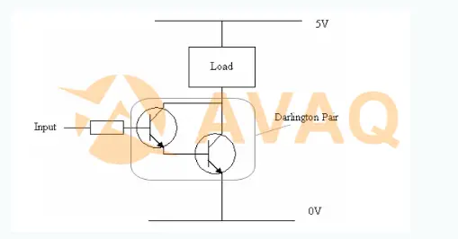
Darlington transistors act as a single transistor with high current gain, which means using a small amount of current from the microcontroller or sensor to run a larger load. For example, in the Darlington circuit below by circuit diagram, it consists of two transistors.
Characteristics of Darlington Transistors
- High current gain
- Low input current requirement
- High input impedance
- Improved linearity
- Reduced base current drive requirements
- Increased input-output isolation
- Slightly higher saturation voltage compared to a single transistor
The Darlington transistor is characterized by high reliability, high stability, high efficiency, low power consumption, and low noise. It can be used for circuit functions such as amplification, filtering and frequency change, and is widely used in electronic equipment, TV sets, radios, computers, communication equipment, etc.
Darlington Transistor Circuit Diagram
The circuit configuration of the Darlington transistor can be used for numerous applications in electrical and electronic circuits.
Darlington's circuits can be used in the form of discrete components, but are also available in various integrated circuit forms, commonly referred to as Darlington transistors. Components for this transistor are available in many forms, including those for high power applications where current levels of many amps may be essential.
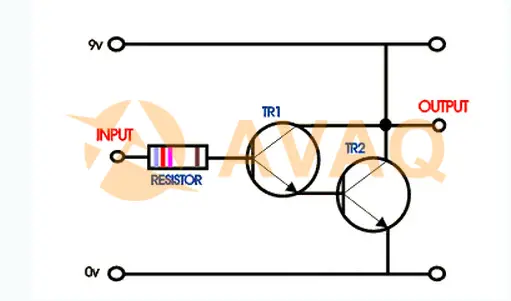
In the diagram above, the basic circuit Darlington can be formed by connecting the input emitter terminal of a triode to the base terminal of a second triode, whose collectors can be connected together. The circuit of this transistor can be used as a single transistor for various circuits, but is mainly used as an emitter follower.
Introduction to Darlington Transistor TIP122
1. What is the TIP122 tube?
TIP122 is a Darlington-to-NPN transistor , consisting of a pair of Darlington transistors, which works similar to an ordinary NPN transistor. The TIP122 is known for its high current gain of 1000, which uses a very high current of 5 A at the collector.
Because of its high current gain and large collector current (IC), the TIP122 is often used in such circuits with high current loads and where high amplification is required.
The TIP122 consumes only 5 V between the base and emitter.
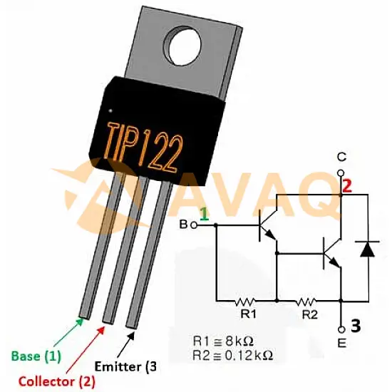
2. TIP122 transistor pin diagram
TIP122 transistor pin diagram includes three pins, each pin and its function will be introduced below.
- Collector (C): Output terminal that collects current when the transistor is on.
- Base (B): Input/control terminal for switching the transistor on/off.
- Emitter (E): Terminal through which current flows out of the transistor.
3. TIP122 CAD model
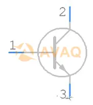
1) TIP122 circuit symbol diagram
2) TIP122 dimensional drawing

3) TIP122 3D model drawing
4. TIP122 Parameter
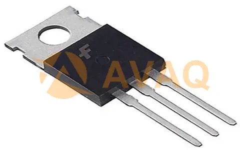
- Package: TO-220
- Transistor Type: NPN Medium Power Darlington Transistor
- High DC current gain (hFE): 1000
- Continuous Collector Current (IC): 5A
- Collector-emitter voltage (VCE): 60V
- Collector-base voltage (VCB): 60V
- Emitter-base voltage (VBE): 5V
- Base current (IB): 120mA
- Collector dissipation (Pc): 65 W
- Peak load current: 8A
- Continuous load current : 5A
- Storage and operating temperature: -65 to +150 ℃
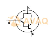
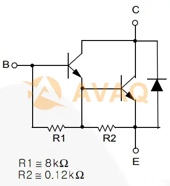
5. TIP122 Operating Principle (Internal Schematic)
As shown in the figure below, the TIP122 TO-220 package has two transistors, the emitter of the first transistor is connected to the base of the second transistor, and the collectors of the two transistors are coupled to form a Darlington pair, which increases the current gain and current rating of the transistor.
6. TIP122 Selection and Replacement
1) TIP122 Equivalent Models
TIP132, TIP102 and more.
The pin configuration of some transistors may be different from TIP122, please check the pin configuration before replacing the circuit.
2)TIP122 Complementary Models
TIP127
3)TIP122 Same type
NPN:TIP120、TIP121、TIP122
PNP: TIP125, TIP126, TIP127
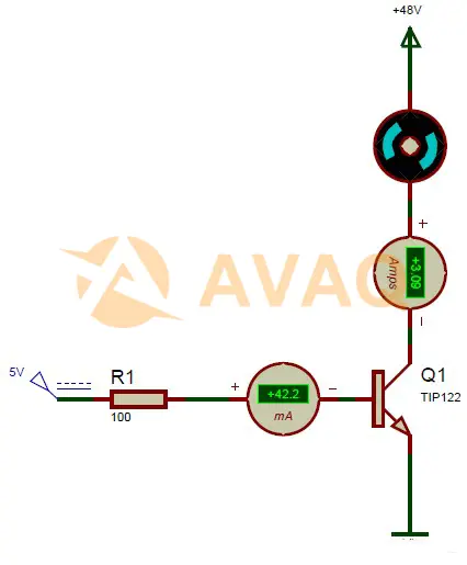
7. TIP122 working principle analog circuit diagram
Although the TIP122 has high collector current and current gain, its control is quite simple because its emitter-base voltage (VBE) is only 5V and the base current is only 120mA. The TIP122 can control a 48V motor with a continuous current of about 3A.
The TIP122 transistor has a continuous collector current of 5A, the load draws only 3A, and the maximum base current is about 120mA, but I used a high resistor value of 100ohm to limit it to 42mA. if your collector current requirements are low, you can even use a 1K resistor.
The TIP122 transistor has a peak (pulse) current of 8A, so make sure your motor does not draw more than that. This is just a model circuit diagram showing how this transistor works, but it cannot be used as such. Therefore, similarly, you can control the load in the same way.
8. TIP122 amplifier circuit diagram explained
The diagram below shows the use of the TIP122 Darlington transistor to build an audio amplifier circuit.
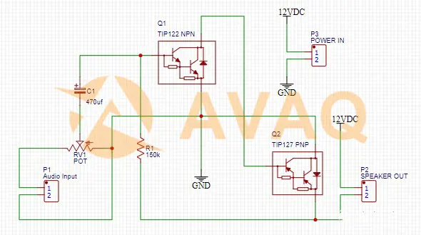
The audio input is taken from a general-purpose audio converter, such as a microphone.
Here, a capacitor (470uF) acts as a coupling capacitor, blocking the DC component of the signal and allowing only the AC component of the signal to pass through.
Transistor Q1 amplifies the signal and sends it to the base of transistor Q2. The TIP122 further amplifies the input signal and directs it to an audio output device, such as a speaker.
You can adjust the strength of the output audio signal by simply adjusting the 10K preset potentiometer.
9. Advantages and Disadvantages of TIP122
1) Advantages of TIP122 Darlington pair transistor
- Provides extremely high current gain compared to a single transistor
- Provides lower noise compared to a phototransistor that contains an external amplifier.
- Provides a very high input impedance.
- By using a current source of a few milliamps, designers can drive more power-based applications.
- Uses fewer components to create the circuit.
- Very sensitive to current.
- Can do signal amplification for a long time.
2) Disadvantages of TIP122 Darlington pair transistor
- Once this transistor is in the saturation region, there is a voltage drop outside the BE terminal.
- The leakage current of the first transistor can be amplified by the second transistor.
- The overall outflow current of the Darlington transistor is higher.
- The switching speed is slow.
- Due to the high saturation voltage, it provides the maximum power consumption.
- Limited bandwidth.
- At certain frequencies, this design can introduce a phase shift in the negative feedback circuit.
Conclusion
In conclusion, Darlington transistors, such as the TIP122, are valuable components in the field of electronics, providing high gain and current amplification for various applications. The TIP122 exemplifies the characteristics of a Darlington transistor with its high current capability and versatile usage in motor control, solenoid driving, and power switching applications.
By understanding the fundamentals of Darlington transistors and exploring the features and advantages of the TIP122, you can effectively harness the capabilities of these components in your circuit designs. Stay updated with the latest advancements, explore datasheets and application notes, and make informed choices when incorporating Darlington transistors, like the TIP122, into your projects. Embrace the performance and versatility of Darlington transistors and unlock new possibilities in electronic circuit design and functionality.
Next Industry Focus
The Easiest Way to Find Low Cost Pressure Sensor
 Update Time: Jul 03, 2023 Consumer Electronics
 FAQ
FAQ
- What are the limitations of Darlington transistors?
- -Higher voltage drop: Due to the presence of two transistors, the voltage drop across a Darlington transistor is higher compared to a single transistor, leading to higher power dissipation. -Slower switching speed: The Darlington configuration introduces additional capacitance, which can result in slower switching speeds compared to a single transistor. -Higher input impedance: The input impedance of a Darlington transistor is higher, which can make it susceptible to noise and instability in high-frequency applications.
- Can Darlington transistors be used in digital circuits?
- Yes, Darlington transistors can be used in digital circuits, especially in applications where high current amplification is required. However, their slower switching speed compared to single transistors should be taken into account when designing high-speed digital circuits.
- Are there any considerations when using Darlington transistors?
- Yes, when using Darlington transistors, it is important to consider factors such as power dissipation, thermal management, and voltage ratings to ensure proper operation. Additionally, care should be taken to avoid excessive base current that could lead to saturation and decreased performance.
Related Industry Focus
-
![Introduction to ABB Thyristor and the Alternative]()
Introduction to ABB Thyristor and the Alternative
ABB thyristors are highly reliable and efficient electronic components that play a crucial role in various power control and switching applications. As one of the leading manufacturers in the industry, ABB offers a wide range of thyristors designed to meet the demanding...
Published: 2023-06-28 17:49:29 -
![4 Best RF HDMI Modulator and How to Choose 2023]()
4 Best RF HDMI Modulator and How to Choose 2023
The demand for high-quality video distribution systems has led to the development of RF HDMI Modulators, which offer a seamless and efficient way to distribute HDMI signals over existing coaxial cable networks. In this article, we will introduce 4 best rf hdmi modulator...
Published: 2023-06-26 18:04:26 -
![Difference between PCB and Integrated Circuit (FAQs)]()
Difference between PCB and Integrated Circuit (FAQs)
Printed Circuit Boards (PCBs) and Integrated Circuits (ICs) are two fundamental components in the world of electronics. Understanding the difference between PCBs and ICs is essential for anyone involved in electronics design and development.
Published: 2023-06-21 17:18:01 -
![Linear and Digital Integrated Circuits: Basics, Application and Difference]()
Linear and Digital Integrated Circuits: Basics, Application and Difference
linear and digital integrated circuits are indispensable components in the world of electronics, in this article, we will explore the world of linear and digital integrated circuits, delving into their fundamental principles, applications, and the key distinctions that ...
Published: 2023-06-19 16:48:35


TIP122G In Stock: 7496
 Popular Industry Focus
Hot Products
-
![MG2040MUTAG]()
MG2040MUTAG
onsemi
ESD Protection Diode, Low Capacitance, High Speed Video Interface
-
![6N136M]()
6N136M
onsemi
High Speed Transistor Optocouplers
-
![1N914BWS]()
1N914BWS
Onsemi
Small Signal Switching Diode 1N914BWS
-
![FQB27P06TM]()
FQB27P06TM
Onsemi
P-Channel Silicon Metal-oxide Semiconductor FET
-
![LM258NG]()
LM258NG
onsemi
General Purpose Amplifier 2 Circuit 8-PDIP
-
![NTMD4N03R2G]()
NTMD4N03R2G
onsemi
Mosfet Array 30V 4A 2W Surface Mount 8-SOIC


Related Parts
-
![IPD25N06S4L-30]()
IPD25N06S4L-30
Infineon
25A High Current N-Channel Transistor for Automotive Applications
-
![STD7NM60N]()
STD7NM60N
Stmicroelectronics
MDmesh II Power MOSFET in DPAK package, featuring N-channel design, 600V voltage tolerance, 0.8 Ohm typical resistance, and 5A current capacity
-
![IRF9321TRPBF]()
IRF9321TRPBF
Infineon Technologies
P-Channel 30 V 15A (Ta) 2.5W (Ta) Surface Mount 8-SO
-
![IRF1404]()
IRF1404
IR
MOSFET MOSFET, 40V, 162A, 4 mOhm, 160 nC Qg, TO-220AB
-
![SPW11N80C3]()
SPW11N80C3
Infineon Technologies Corporation
N-Channel MOSFET Transistor
-
![BFR520]()
BFR520
Nxp
1.1dB 9GHz 16dB UHF microwave ,CATV,UHF,VHF SOT-23 RF Amplifiers ROHS
-
![PTFB182503FL]()
PTFB182503FL
INFINEON
RF Power Field-Effect Transistor,
-
![STP20NM50]()
STP20NM50
Stmicroelectronics
N-channel 500V power MOSFET
-
![C3M0021120K]()
C3M0021120K
WOLFSPEED, INC.
N-Channel 1200 V 100A (Tc) 469W (Tc) Through Hole TO-247-4L
-
![FQA28N50F]()
FQA28N50F
Onsemi
Transistor MOSFET
-
![SPW17N80C3]()
SPW17N80C3
Infineon
800V N-Channel MOSFET with a maximum current rating of 17A
-
![BUK9Y3R0-40E]()
BUK9Y3R0-40E
NXP
Trans MOSFET N-CH 40V 100A Automotive 5-Pin(4+Tab) LFPAK
-
![BFU668F]()
BFU668F
NXP
NPN wideband silicon RF transistor
-
![PSMN025-100D]()
PSMN025-100D
Nexperia
100V Plastic DPAK-3
-
![IPT059N15N3]()
IPT059N15N3
INFINEON
N-Channel 150 V 155A (Tc) 375W (Tc) Surface Mount PG-HSOF-8-1


Featured Manufacturers