Payment Method


Buck, Push-Pull Regulator Positive Output Step-Down, Step-Up/Step-Down DC-DC Controller IC 16-SOIC
Manufacturer:
Mfr.Part #:
TL594CDR2G
Datasheet:
Case Outline:
948F-01
MSL Temp (°C):
260
Container Type:
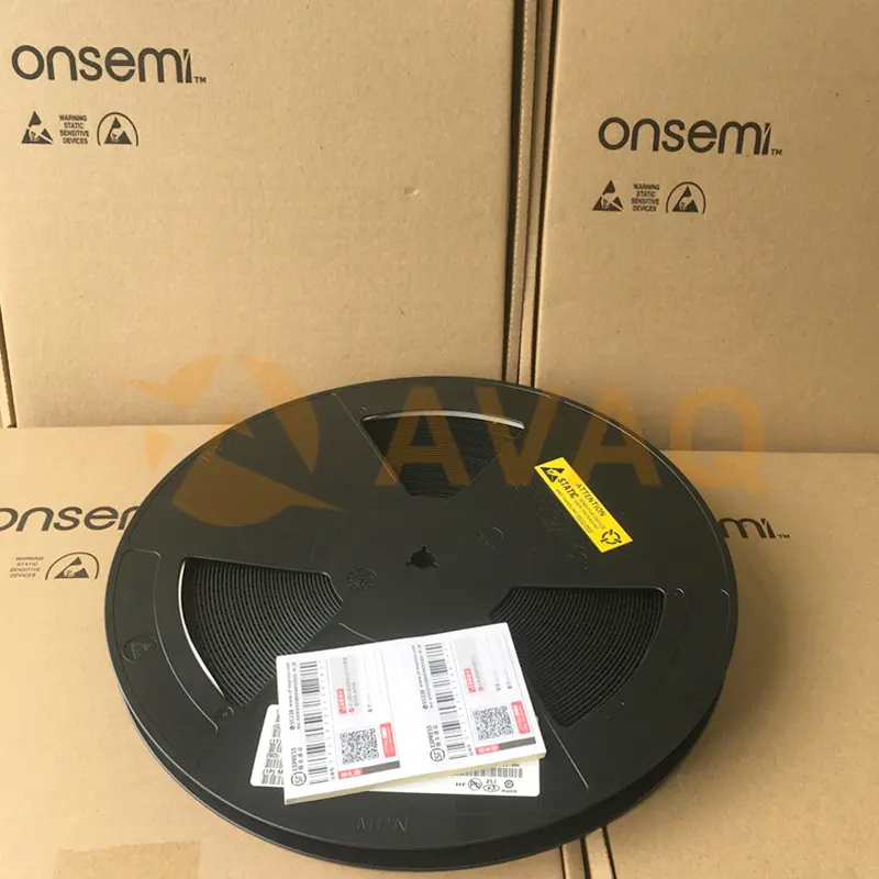
REEL
Topology:
Push-Pull
EDA/CAD Models:
Please fill in the short form below and we will provide you the quotation immediately.
The TL594 PWM Controller incorporates all the functions required in the construction of a pulse width modulation (PWM) control circuit on a single chip. Designed primarily for power-supply control, this device offers the systems engineer the flexibility to tailor the power-supply control circuitry to a specific application.
The TL594 PWM Controller contains two error amplifiers, an on-chip adjustable oscillator, a dead-time control (DTC) comparator, a pulse-steering control flip-flop, a 5-V regulator with a precision of 1.5%, an undervoltage lockout control circuit, and output control circuitry.
The error amplifiers have a common-mode voltage range of -0.3 V to VCC-2 V. The DTC comparator has a fixed offset that provides approximately 5% dead time. The on-chip oscillator can be bypassed by terminating RT to the reference output and providing a sawtooth input to CT, or it can be used to drive the common circuitry in synchronous multiple-rail power supplies.
The uncommitted output transistors provide either common-emitter or emitter-follower output capability. Each device provides for push-pull or single-ended output operation, with selection by means of the output-control function. The architecture of these devices prohibits the possibility of either output being pulsed twice during push-pull operation. The undervoltage lockout control circuit locks the outputs off until the internal circuitry is operational.
The TL594CD, CN, CDTB are characterized for operation from -40C to 85C.


| Status | Active | Case Outline | 948F-01 |
| MSL Temp (°C) | 260 | Container Type | REEL |
| Product Category | Switching Controllers | Topology | Push-Pull |
| Number of Outputs | 1 Output | Switching Frequency | 40 kHz |
| Duty Cycle - Max | 48 % | Input Voltage | 15 V |
| Output Voltage | - | Output Current | 500 mA |
| Minimum Operating Temperature | - 40 C | Maximum Operating Temperature | + 85 C |
| Mounting Style | SMD/SMT | Fall Time | 40 ns |
| Height | 1.5 mm | Isolation | Non-Isolated |
| Length | 10 mm | Operating Supply Current | 11 mA |
| Operating Supply Voltage | 15 V | Product | Switching Controllers |
| Product Type | Switching Controllers | Rise Time | 100 ns |
| Series | TL594 | Factory Pack Quantity | 2500 |
| Subcategory | PMIC - Power Management ICs | Type | Voltage Mode PWM Controller |
| Unit Weight | 0.023492 oz |
After-Sales & Settlement Related
 Payment
Payment Method


For alternative payment channels, please reach out to us at:
[email protected] Shipping & Packing
Shipping Method


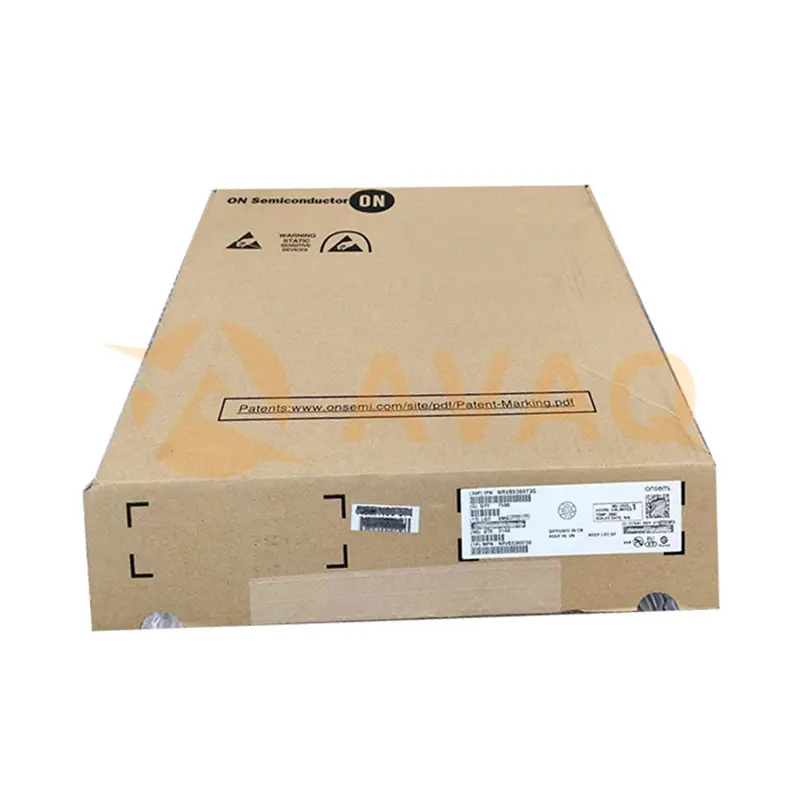
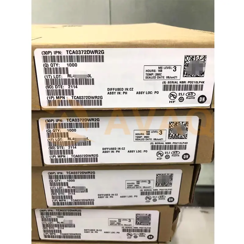
AVAQ determines and packages all devices based on electrostatic discharge (ESD) and moisture sensitivity level (MSL) protection requirements.
 Warranty

365-Day Product
Quality Guarantee
We promise to provide 365 days quality assurance service for all our products.
| Qty. | Unit Price | Ext. Price |
|---|---|---|
| 1+ | $0.761 | $0.76 |
| 10+ | $0.630 | $6.30 |
| 30+ | $0.564 | $16.92 |
| 100+ | $0.496 | $49.60 |
| 500+ | $0.457 | $228.50 |
| 1000+ | $0.438 | $438.00 |
The prices below are for reference only.
All bill of materials (BOM) can be sent via email to ![]() [email protected],
or fill below form to Quote for TL594CDR2G, guaranteed quotes back within
[email protected],
or fill below form to Quote for TL594CDR2G, guaranteed quotes back within
![]() 12hr.
12hr.