L293D Motor Driver Board: Price, Pinout and Datasheet
 Published: Aug 30, 2023
Contents
The L293D motor driver board stands as a crucial component in the world of robotics and automation, serving as a bridge between microcontrollers and motors. In this article, we will introduce the pricing, pinout configuration, and datasheet specifications of the L293D motor driver IC, let’s explore it.
L293D Motor Driver Board Description
The L293D Motor Driver Board is a compact circuit board designed to facilitate the control of DC motors and other similar devices using the L293D motor driver IC. It simplifies the process of interfacing motors with microcontrollers, Arduino boards, or other control systems.

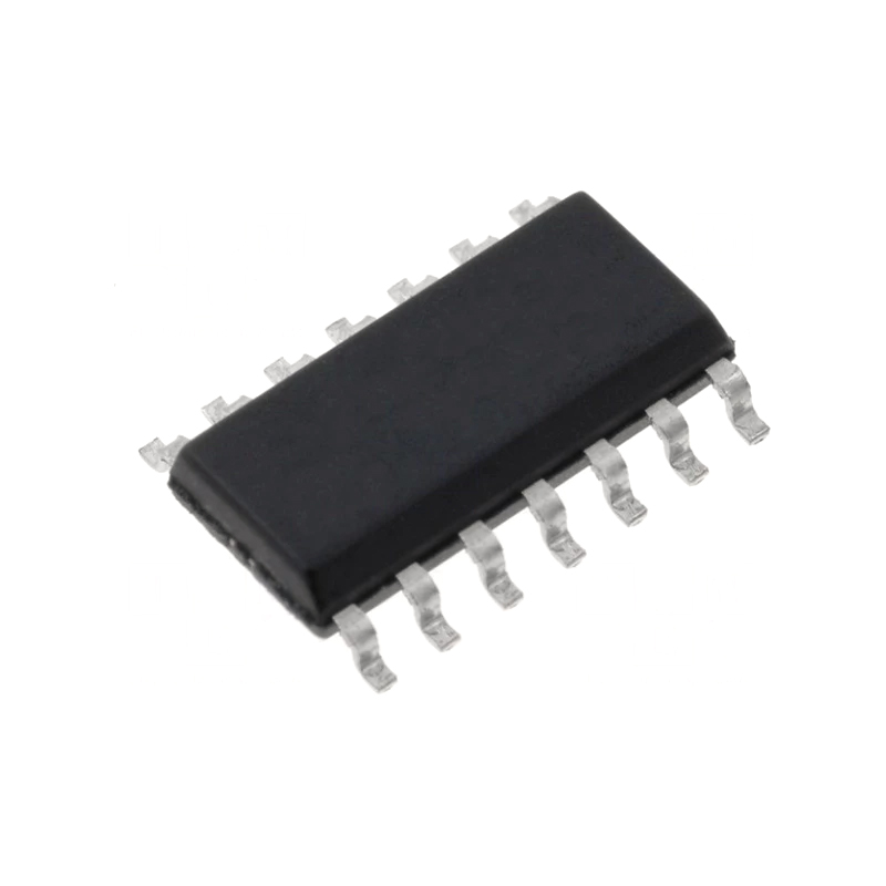
L293D motor driver board
L293D Motor Driver IC
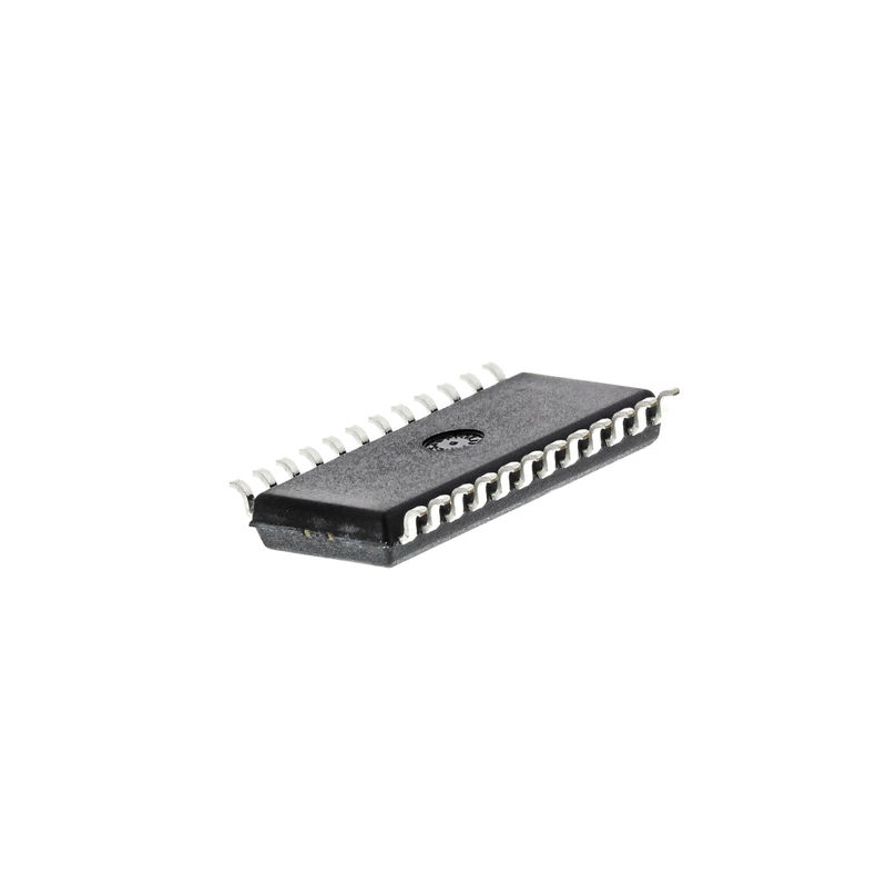
The L293D is a dual H-bridge motor driver IC, capable of controlling the movement of two DC motors or a single stepper motor. Each H-bridge allows bidirectional control, enabling motors to move forward or backward. The IC can handle peak currents of up to 600mA and continuous currents of around 350mA, making it suitable for a range of small to moderate-sized motors.
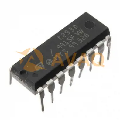
L293D motor driver ic
L293D Motor Driver Board Price
The price of an L293D Motor Driver Board typically ranged from a few dollars to around $10 USD.
However, prices can fluctuate due to factors like availability, demand, and any new product releases.
L293D Motor Driver IC Specifications and Features
L293D Motor Driver IC Specifications:
- Supply Voltage Range: 4.5 V to 36 V
- Input-Logic Supply: Separate
- ESD Protection: Internal
- High Noise Immunity: Yes
- Output Current: 600 mA per channel
- Peak Output Current: 1.2 A per channel
- Output Clamp Diodes: Included
- Operating Temperature: 0°C to 70°C
- Automatic Thermal Shutdown: Yes
key features of the L293D Motor Driver IC
- Bidirectional control for two DC motors or one stepper motor.
- High peak current handling: 600mA.
- Continuous current support: 350mA.
- Built-in protection diodes for voltage spike suppression.
- Logic-level compatibility (TTL and CMOS).
- Enable pins for independent motor control.
- Separate power supplies for motors and logic.
- Thermal shutdown protection.
- Wide motor voltage range: 4.5V to 36V.
- Compact design for easy integration.
- Cost-effective solution for motor control applications.
L293D Motor Driver IC Pinout
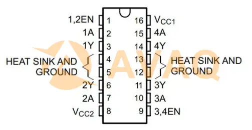
L293D motor driver pinout
|
Pin |
Name |
Description |
|
1 |
1,2EN |
Enable driver channels 1 and 2 (active high input) |
|
2 |
<1:4>A |
Driver inputs, noninverting (for channels 1, 2, 3, and 4) |
|
3 |
<1:4>Y |
Driver outputs (corresponding to channels 1, 2, 3, and 4) |
|
4 |
3,4EN |
Enable driver channels 3 and 4 (active high input) |
|
5 |
GROUND |
Device ground and heat sink pin (connect to PCB ground plane) |
|
6 |
GROUND |
Device ground and heat sink pin (connect to PCB ground plane) |
|
7 |
<1:4>A |
Driver inputs, noninverting (for channels 1, 2, 3, and 4) |
|
8 |
VCC2 |
Power supply for drivers (4.5 V to 36 V) |
|
9 |
3,4EN |
Enable driver channels 3 and 4 (active high input) |
|
10 |
<1:4>A |
Driver inputs, noninverting (for channels 1, 2, 3, and 4) |
|
11 |
<1:4>Y |
Driver outputs (corresponding to channels 1, 2, 3, and 4) |
|
12 |
GROUND |
Device ground and heat sink pin (connect to PCB ground plane) |
|
13 |
GROUND |
Device ground and heat sink pin (connect to PCB ground plane) |
|
14 |
<1:4>Y |
Driver outputs (corresponding to channels 1, 2, 3, and 4) |
|
15 |
<1:4>A |
Driver inputs, noninverting (for channels 1, 2, 3, and 4) |
|
16 |
VCC1 |
5-V supply for internal logic translation |
How Does L293D Motor Driver Work
The L293D Motor Driver IC's functionality involves regulating the movement and direction of connected motors based on input signals. There are four input pins responsible for direction control: pins 2 and 7 (1A and 2A) on the left side, and pins 15 and 10 (3A and 4A) on the right side of the IC.
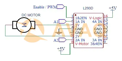
L293D Motor Driver IC working
To clarify the working principle with an example, consider a motor connected to the left output pins (pin 3 and pin 6). To control this motor's rotation, input logic is applied to pins 2 and 7 (1A and 2A).
Here are the control scenarios:
- Clockwise Direction: Set Pin 2 to HIGH and Pin 7 to LOW.
- Counter Clockwise Direction: Set Pin 2 to LOW and Pin 7 to HIGH.
- Idle - No Rotation: Set both Pin 2 and Pin 7 to either LOW or HIGH.
- Similarly, the motor on the right side, connected to pins 11 and 14, can be controlled using pins 10 and 15.
The corresponding control scenarios for the right motor are:
- Clockwise Direction: Set Pin 10 to HIGH and Pin 15 to LOW.
- Counter Clockwise Direction: Set Pin 10 to LOW and Pin 15 to HIGH.
- Idle - No Rotation: Set both Pin 10 and Pin 15 to either LOW or HIGH.
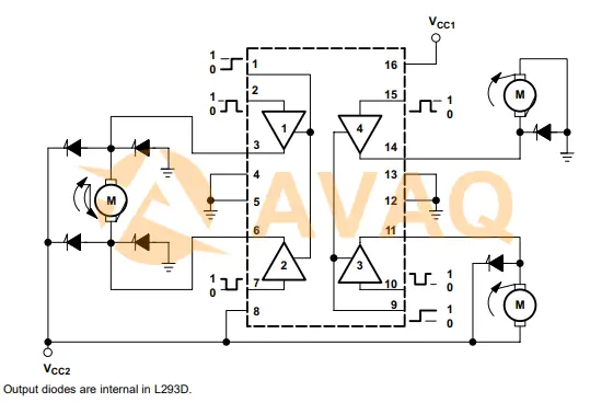
L293D Motor Driver Application
Typical Application of L293D:
The Two-Phase Motor Driver (L293) is designed to efficiently control and drive two-phase stepper motors. It's commonly used in applications where precise and synchronized motor movement is required, such as robotics, CNC machines, 3D printers, and automated systems. The L293 motor driver provides bi-directional control, allowing for accurate control of motor rotation and position.
L293D application
Other application of L293D:
Robotics: The L293D is widely used in robotics for driving and controlling the movement of robotic platforms and arms.
Automated Systems: It's utilized in automated systems where controlled motor motion is required, such as conveyor belts and automated doors.
Hobbyist Projects: The motor driver is a favorite among hobbyists for creating remote-controlled cars, drones, and other motor-driven projects.
CNC Machines: In computer numerical control (CNC) applications, the L293D can be used to control the movement of stepper motors in precision machining.
Actuators: The motor driver is employed in various applications requiring precise actuation, such as motorized valves and linear actuators.
Remote-Controlled Vehicles: It's commonly used in remote-controlled cars, boats, planes, and other vehicles to manage motor speed and direction.
Automation Systems: The L293D can be found in systems that require automation, like smart home devices and industrial machinery.
Educational Projects: It's frequently used in educational settings to teach students about motor control, electronics, and microcontroller interfacing.
Pan-and-Tilt Mechanisms: The motor driver can be used to control the movement of camera platforms, like pan-and-tilt mechanisms.
Motorized Displays: In applications like motorized signage or displays, the L293D can control the motion of moving parts.
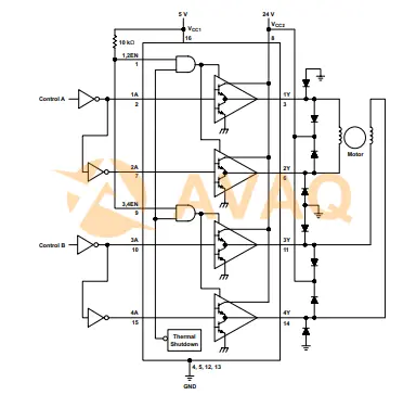
L293D Motor Driver Functional Block Diagram
L293D motor driver block diagram
L293D Motor Driver IC Datasheet
Download L293D motor driver ic datasheet>>
Conclusion
In conclusion, the L293D motor driver board represents an essential tool in the arsenal of robotics and automation enthusiasts, enabling precise motor control with simplicity and efficiency. L293D IC pinout configuration and comprehensive datasheet resources empower designers to seamlessly integrate motor control into their applications.
Whether you are building robots, automated vehicles, or motion-controlled systems, the L293D motor driver board will undoubtedly play a pivotal role in enhancing the motor control precision and versatility of your electronic designs.
Next Industry Focus
TAS2560 IC: Datasheet, Features, Diagram and Application
 Update Time: Sep 04, 2023 Consumer Electronics
 FAQ
FAQ
- Are there alternatives to the L293D motor driver board?
- Yes, there are other motor driver ICs and boards available, such as the L298N and L298P, which provide similar motor control capabilities.
- Is the L293D motor driver board suitable for robotic applications?
- Yes, the L293D motor driver board is commonly used in robotic applications to control the movement of motors and wheels.
- What is the maximum current the L293D motor driver board can handle?
- The maximum current handling of the L293D motor driver board depends on the specific variant of the L293D IC being used and the power supply voltage. Generally, it can handle currents up to 600 mA per channel.
- Can the L293D motor driver board handle high-power motors?
- The L293D motor driver board is suitable for low to medium-power motors. For high-power applications, additional heat sinks and considerations for current limits might be necessary.
Related Industry Focus
-
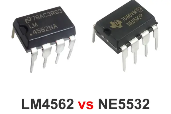
LM4562 vs NE5532: What are Differences and How to Choose
The comparison between the LM4562 and NE5532 operational amplifiers (op-amps) is an essential journey into the world of audio electronics, where the intricacies of sound quality and performance are paramount. In this article, we will delve into the distinctions between ...
Published: 2023-08-28 16:07:52 -
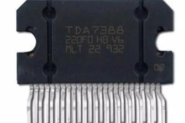
TDA7388 Amplifier: Pinout, Datasheet and Voltage
The TDA7388 is a quad-channel audio power amplifier integrated circuit (IC) designed for use in various audio applications, in this article, we will delve into the pinout configuration, datasheet specifications, and voltage requirements of the TDA7388 amplifier.
Published: 2023-08-23 18:26:09 -
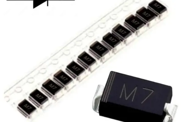
1N4007 SMD Diode: Equivalent, Datasheet PDF and Specs
The 1N4007is a common rectifier diode that is widely used in electronic circuits to convert alternating current (AC) to direct current (DC). In this article, we will delve into the equivalent options, datasheet resources, and specifications of the 1N4007 SMD diode.
Published: 2023-08-21 18:13:16 -
NE5532 vs TL072: What are Differences and How to Choose 2023
The NE5532 and TL072 are two prominent operational amplifiers (op-amps) that have earned their place in the world of electronics for their versatile performance and widespread applications. In this article, we will delve into the distinctions between the NE5532 and TL07...
Published: 2023-08-18 18:01:28
L293DD In Stock: 6503
 Popular Industry Focus
Hot Products
-
TS613IDT
STMicroelectronics, Inc
Voltage Feedback Amplifier 2 Circuit 8-SO
-

M48Z12-70PC1
STMicroelectronics, Inc
NVSRAM (Non-Volatile SRAM) Memory IC 16Kbit Parallel 70 ns 24-PCDIP, CAPHAT®
-
BLUENRG-355MT
STMicroelectronics, Inc
Programmable Bluetooth® LE 5.2 Wireless SoC
-
TSM1011AIDT
STMicroelectronics, Inc
Series Voltage Reference IC Fixed 2.545V V ±1% 1 mA 8-SOIC
-
STWBC
STMicroelectronics, Inc
Digital Power Controller PMIC 32-VFQFPN (5x5)
-
L6564D
STMicroelectronics, Inc
PFC IC Discontinuous (Transition) 10-SSOP
Related Parts
-
HV9910CNG-G
Microchip Technology, Inc
Universal High-Brightness LED Driver.
-
TLD1121ELXUMA1
Infineon Technologies Corporation
LED Driver IC 1 Output Linear Dimming 360mA PG-SSOP-14-EP
-
MIC2292-15YML-TR
Microchip Technology, Inc
1.6MHz White LED Driver w/34V OVP.
-
STV7697B
STMicroelectronics, Inc
Plasma Driver 5V 0.0058A 8MHz 100-Pin TQFP Tray
-
UBA2211AT/N1,518
NXP Semiconductor
Non-dimmable driver IC for CFL
-
TW8816-LB3-GRS
Renesas Technology Corp
Video Processor IC GPIO, I²C, SPI, Serial NTSC, PAL, SECAM 128-LQFP (14x20) Package
-
PCA9532D,118
NXP Semiconductor
I2C 5 V Voltage Source LED Blinker
-
LC75812PTH-8565-H
ON Semiconductor, LLC
LCD Driver 100-TQFP (14x14)
-
LC75838WS-E
ON Semiconductor, LLC
LCD Drivers LCD Driver, 1/8 to 1/10 Duty, General-Purpose
-
BCR601XUMA1
Infineon Technologies Corporation
LED Driver IC 1 Output Linear Flyback Analog Dimming 10mA PG-DSO-8
-
TPS61177ARGRR
Texas Instruments, Inc
WLED driver for notebook and Tablet display
-
LC75884WHS-E
ON Semiconductor, LLC
LCD Drivers LCD DISPLAY DVR
-
CP2401-GQR
Silicon Laboratories Inc
LCD Driver 48-TQFP (7x7)
-
LC75812PTS-8565-H
ON Semiconductor, LLC
LCD Driver 100-TQFP (14x14)
-
ICM7211AIQH+D
Maxim Integrated
LCD Driver 44-PLCC (16.59x16.59)
Featured Manufacturers