How to Generate Square Wave Generator Using 555 Timer
 Published: Jul 21, 2023
Contents
A square wave generator using the 555 timer is a popular and versatile electronic circuit used to produce square wave signals with precise frequency and duty cycle control. The 555 timer IC is widely known for its flexibility and ease of use in various timing applications, and it can be configured as an astable multivibrator to generate square wave signals.
In this article, we will explore what is square wave generator, what is 555 timer and how to generate a square wave generator using 555 timer. Whether you are an electronics enthusiast, a hobbyist, or a professional engineer, understanding how to build a square wave generator using the 555 timer will empower you to create precise and reliable square wave signals for your electronic projects.
What is Square Wave Generator
A square wave generator is an electronic circuit or device used to produce a specific type of waveform called a square wave. The square wave is a non-sinusoidal waveform that alternates between two voltage levels in a rapid and periodic manner.
A typical square wave has a 50% duty cycle, meaning the waveform spends an equal amount of time at its high and low voltage levels. The voltage transitions between these two levels are instantaneous, creating sharp, square-like edges, hence the name "square wave."
Square wave generators are commonly used in various applications, including:
- Digital systems testing: They are used to simulate digital signals for testing and debugging digital circuits.
- Signal processing: Square waves can be used in applications like pulse-width modulation (PWM) to control power levels, motor speed, or light intensity.
- Clock signals: In digital electronics, square wave generators are often employed to generate clock signals used to synchronize the operation of various components in a system.
- Communication systems: In some cases, square waves can be used in communication protocols or signal encoding schemes.
What is 555 Timer
The 555 timer is a widely used integrated circuit (IC) that functions as a versatile timer, pulse generator, and oscillator. It was introduced by Signetics (now part of ON Semiconductor) in 1972 and has since become one of the most popular ICs in electronics due to its simplicity, reliability, and wide range of applications.
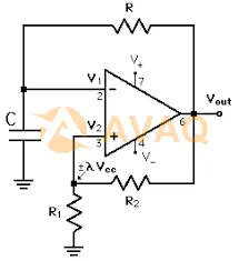
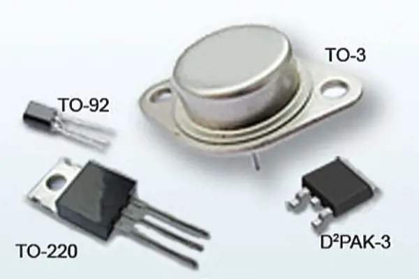
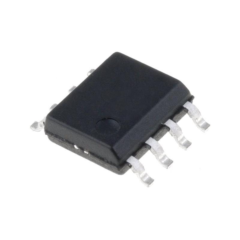
The 555 timer is an 8-pin IC and can be found in various package types, such as the dual in-line package (DIP) or surface-mount package (SMD). The internal architecture of the 555 timer consists of two voltage comparators, an SR flip-flop, a discharge transistor, and resistors and capacitors for timing control.
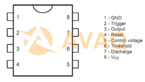
555 Time IC Pin Diagram
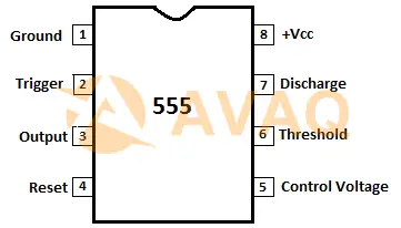
Pin 1 (GND): Ground pin, connected to the negative terminal of the power supply.
Pin 2 (TRIG): Trigger pin. This is an input pin used to initiate the timing cycle or trigger the one-shot operation. When the voltage at this pin falls below a third of the supply voltage (Vcc), the timer is triggered.
Pin 3 (OUT): Output pin. The output of the 555 timer is available at this pin. In astable mode, it produces a continuous square wave, while in monostable mode, it generates a pulse with a width determined by the external timing components.
Pin 4 (RESET): Reset pin. When a voltage is applied to this pin, it resets the internal flip-flop, stopping the timing operation.
Pin 5 (CTRL): Control voltage pin. This pin allows an external voltage to modulate the timing characteristics of the 555 timer, such as frequency and duty cycle. In most applications, this pin is connected to Vcc.
Pin 6 (THRESH): Threshold pin. This is an input pin used to reset the internal flip-flop and stop the timing cycle when the voltage at this pin exceeds two-thirds of the supply voltage (Vcc).
Pin 7 (DISCH): Discharge pin. This is an open-drain output pin used to discharge the external timing capacitor to ground during the timing cycle. It is also used to discharge the capacitor in the one-shot operation.
Pin 8 (Vcc): Supply voltage pin. The positive terminal of the power supply is connected to this pin.
Types of 555 Timer
|
Type |
Manufacturer |
Features |
Applications |
|
Multiple |
Standard version, wide voltage range |
Timing circuits, pulse generation, oscillators |
|
|
ICM7555 |
Intersil/Maxim |
Low-power CMOS, reduced supply current |
Battery-operated devices, low-power applications |
|
TLC555 |
Texas Instruments |
Low-power CMOS, improved performance |
Battery-powered devices, precision timing |
|
LMC555 |
Texas Instruments |
Precision version, enhanced accuracy |
Precision timing applications, signal processing |
|
SE555 |
Multiple |
Extended temperature range operation |
Industrial applications, harsh environments |
|
NE555V |
Multiple |
Extended temperature range operation |
Industrial applications, harsh environments |
|
Intersil/Maxim |
Dual CMOS timers in one package |
Dual timer applications, multivibrator circuits |
|
|
LMC556 |
Texas Instruments |
Dual precision timers in one package |
Precision timing applications, control systems |
|
LM556 |
Texas Instruments |
Dual version of NE555 |
Dual timer applications, multivibrator circuits |
How to Generate a Square Wave Generator Using 555 Timer
The principle is that the DC power oscillation after boosting, for example, 1 small power electric stick, the use of 6V-12V DC power supply can produce a kind of high-voltage pulse. Circuit transistor Q1, Q2 constitutes an oscillator, generating a frequency of 3Hz DC pulse voltage, and input transformer ratio of 6V: 240V booster primary coil, at the end of each pulse, accordingly, in the secondary coil of the transformer to produce a high voltage. The repetition frequency of the pulses can be adjusted by selecting the values of C2 and R1.
As shown below:
Step1. Second Signal Generation Circuit
The second signal generation circuit consists of a polytuned oscillator composed of an IC 555 timer and an RC. The chips needed are the IC 555 timer, as well as resistors and capacitors. The following figure shows its circuit diagram:
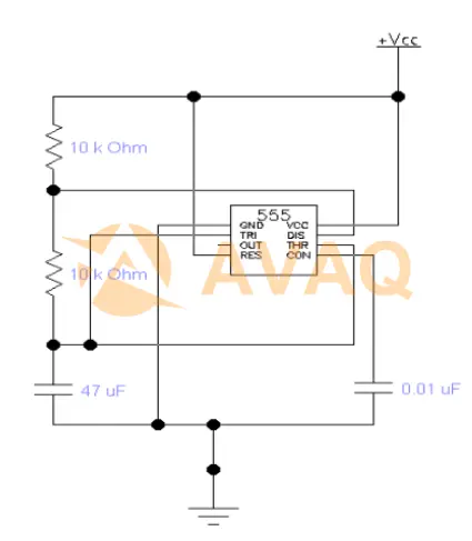
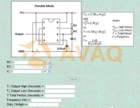
Oscillation circuit is the core part of the digital clock, its frequency and stability are directly related to the accuracy of the meter. Therefore, choose the 555 timer composition of the polyharmonic oscillator, which capacitance C1 is 47 microfarads, C2 is 0.01 microfarads, two resistors R1 = R2 = 10K ohms. At this point at the output of the circuit a periodic rectangular wave is obtained with an oscillation frequency of:
f=1.43/[(R1+2R2)C] (3-1)
From the formula (3-1) by substituting the value of R1 , R2 and C, f = 1Hz. that is, its output frequency is 1Hz rectangular wave signal.
Step2. Make a second pulse with 555
The output frequency is 1Hz and the duty cycle is 50%.
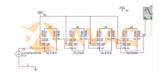
Since the CD4060 cannot be simulated in MULTISIM, this design uses three 74HC161 and one 74HC160IC in cascade to form a 2^15 divider. The unit circuit connection is shown below:
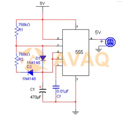
Step3. NE555-based second square wave generator design
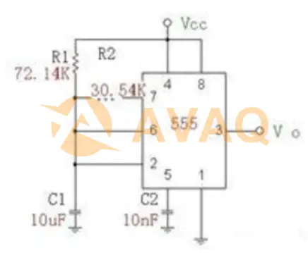
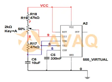
The NE555 chip and peripheral circuits are used to build a polyharmonic oscillator, and the output square wave frequency is 1Hz by designing the parameters of the peripheral circuits, so it is called a second square wave generator. As the duty cycle of the pulse has little effect on the system, the duty cycle is designed as 1/3. the output square wave is used as the clk signal of the counter and the D flip-flop. the pin diagram of the NE555 timer is shown in Fig. 1, and the pulse frequency formula:
f = 1 / (R1 + 2R2) C㏑2
R1=47K, R2=47K, RV1=2K, and C=10μF were selected to form the circuit diagram shown in Figure 2:
Existing 0.01uF 1uF 10uF capacitor each, 6.8k 1k 330 ohm resistor each two, how to use 555 to generate 1Hz square wave pulse
R1 with 330 ohms, R2 with 6.8K ohms, C with 0.1uF555 pin 3 output square wave period T = 0.7 (R1 + 2R2) C = 0.7x (0.33 + 2x6.8) x 0.1 = 0.9751
Square wave frequency F=1/T=1/0.9751=1.0255Hz
Conclusion
In conclusion, a square wave generator using the 555 timers provides a simple yet effective way to generate square wave signals with controllable frequency and duty cycle. This versatile circuit finds applications in various areas, such as signal processing, waveform testing, and communication systems. When building a square wave generator, consider factors such as the desired frequency range, duty cycle requirements, and the specific application to ensure optimal performance.
Stay updated with the latest advancements in timer IC technology, explore datasheets and technical documentation, and make informed choices when designing your square wave generator. Embrace the functionality and convenience offered by this circuit and unlock new possibilities in signal generation and electronic design. Whether you are working on educational projects, audio applications, or digital circuits, the square wave generator using the 555 timer is an invaluable tool for generating precise square wave signals.
Next Industry Focus
5 Best Audio Amplifier IC in the Market 2023
 Update Time: Jul 24, 2023 Consumer Electronics
 FAQ
FAQ
- Can I adjust the output voltage level of the square wave generated by a 555 timer?
- The 555 timer IC operates with a fixed output voltage range based on its power supply voltage. The output voltage level of the square wave generated depends on the supply voltage and the load connected to the output pin. If necessary, additional circuitry, such as voltage level shifters or amplifiers, can be used to modify the output voltage level.
- Can the frequency and duty cycle of the square wave be adjusted?
- Yes, the frequency and duty cycle of the square wave can be adjusted by varying the values of the resistors and capacitors in the circuit. Changing the resistor values alters the timing period, and modifying the capacitor value changes the charging and discharging times, consequently affecting the frequency and duty cycle.
- How does the 555 timer function as a square wave generator?
- The 555 timer can be configured as an astable multivibrator by connecting external resistors and capacitors to its pins. In this configuration, the 555 timer continuously oscillates between its high and low states, producing a square wave output.
- What is a square wave generator using a 555 timer?
- A square wave generator using a 555 timer is an electronic circuit that produces a square wave output signal. The 555 timer IC is configured as an astable multivibrator to generate the square wave, which has a fixed amplitude and alternates between two voltage levels (high and low) in a regular and symmetrical pattern.
Related Industry Focus
-
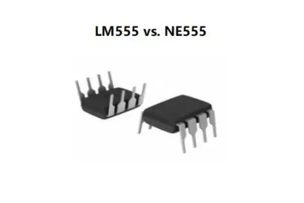
LM555 vs NE555: Are They Equivalent and Main Differences
The LM555 and NE555 are two commonly used integrated circuits (ICs) known as timers or oscillators, widely employed in various electronic applications. In this article, we will explore the similarities and differences between the LM555 and NE555 ICs, shedding light on t...
Published: 2023-07-20 14:25:43 -
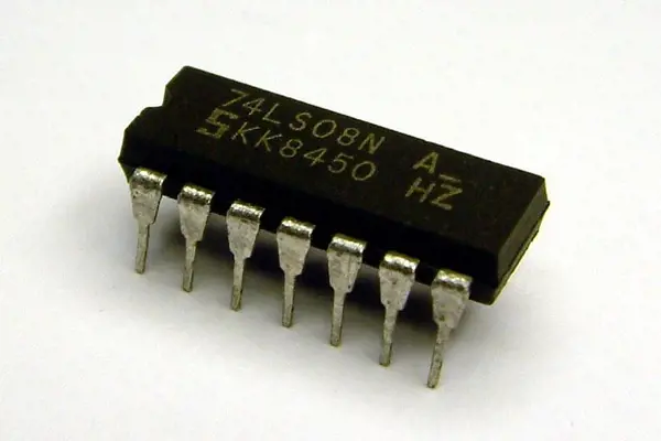
7408 Integrated Circuit: Pinout, Datasheet and Equivalent
The 7408 integrated circuit (IC), also known as a quad 2-input AND gate, is a widely used component in digital logic circuits. In this article, we will explore the pinout, datasheet, and equivalent options for the 7408 IC, providing valuable insights for electronics ent...
Published: 2023-07-17 17:28:35 -
What is Static Voltage Regulator
A static voltage regulator is an electronic device that maintains a constant output voltage by adjusting the current flow in response to changes in input voltage or load conditions. In this article, we will explore the different types, working principle, and application...
Published: 2023-07-14 15:36:26 -
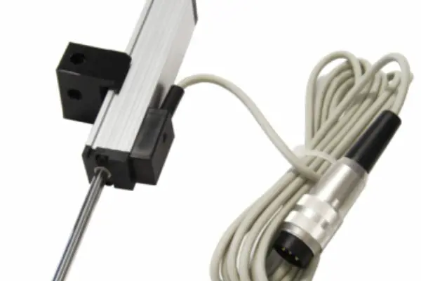
Linear Displacement Transducer: Types, Working Principle and Application
A linear displacement transducer, also known as a linear position sensor or linear encoder, is a crucial component in various industries and applications where precise measurement and control of linear motion are required. In this article, we will explore the different ...
Published: 2023-07-12 17:16:17
LM555CM/NOPB In Stock: 4313
 Popular Industry Focus
Hot Products
-
AX-SFAZ-API-1-01-TX30
ON Semiconductor, LLC
IC RF TxRx + MCU General ISM < 1GHz SIGFOX™ 922MHz 40-VFQFN Exposed Pad
-
A5191HRTLg
ON Semiconductor, LLC
Modem Chip Hart Single 1.2Kbps 32-Pin LQFP
-
LMV393DR2G
ON Semiconductor, LLC
Comparator, Dual, Low Voltage
-
LV3313PM-TLM-E
ON Semiconductor, LLC
Audio Volume Control 4 Channel 44-QIPM (10x10)
-
LMV331SN3T1G
ON Semiconductor, LLC
Comparator, Single, Low Voltage
-
LA1867NM-MPB-E
ON Semiconductor, LLC
Car Radio Single-Chip Tuner System
Related Parts
-

NEO-M8T-0-01
U-BLOX AG
GPS Receiver 1575.42MHz 3.6V 24-Pin T/R
-
PTN3392BS/F3
NXP Semiconductor
NXP Semiconductors PTN3392BS/HVQFN48//F3/REEL 13 Q1/T1 *STANDARD MAR
-
PTN3355BS
NXP Semiconductor
Low power DisplayPort to VGA adapter with integrated 1 : 2 VGA switch
-
HI-1590PCI
Holt Integrated Circuits
Dual Transceiver 1TX 1RX 44-Pin QFN EP
-
FDC37C666
Microchip Technology, Inc
I/O Controller IC
-
LPC47B272
Microchip Technology, Inc
Super I/O Controller.
-
BLP15H9S100GZ
Ampleon
Trans RF FET N-CH 106V 3-Pin TO-270 T/R
-
LSISAS1064E-LEADFREE
Broadcom Corporation
PCI SCSI Controller PCI/Flash Memory 636-Pin EPBGA
-
WP413808 SLJ7B
Intel Corp
I/O Controller 1357-Pin FCBGA
-
NVVR26A120M1WSS
ON Semiconductor, LLC
Silicon Carbide (SiC) Module - EliteSiC Power Module for Traction Inverter, Single-Side Cooling, 2.6mΩ Rds_on, 1200V, Half-Bridge, Straight Power Tabs
-
HGTP14N44G3VL
ON Semiconductor, LLC
Trans IGBT Chip N-CH 490V 27A 231mW 3-Pin(3+Tab) TO-220AB T/R
-
IGC50T120T8RQX1SA1
Infineon Technologies Corporation
IGBT Trench Field Stop 1200 V Surface Mount Die
-
SKiiP 24NAB12T4V10
Semikron, Inc
MiniSKiip; 1200V; 50A | SEMIKRON SKIIP 24NAB12T4V10
-
HCT4053
HARRIS
8-channel analog multiplexer/demultiplexer
-
XC6202P502MR
TOREX
LDO Voltage Regulators Volt. Reg. 5.0v, SOT-23
Featured Manufacturers